In metal fabrication and engineering, the ‘Limits and Fits’ concept is the foundation for attaining precision in manufactured parts. Limits and fits refer to the designated allowances and tolerances that dictate the dimensional accuracy of mating components. Understanding and applying these principles ensures that these components assemble correctly and function as intended.
Components may be too tight without strict adherence to these specifications, leading to seizing or too loose, resulting in excessive play and wear. As engineers and manufacturers strive for innovations that push the boundaries of technology and design, mastering limits and mechanical fits and tolerances remain critical in ensuring the final product’s quality, reliability, and performance.
What are the Various Types of Engineering Fits?
- Clearance fits indicate a positive space between an assembled hole and the shaft, avoiding friction-induced wear and overheating when the parts are at their size limits. This fit allows for free movement and easy assembly or disassembly, ideal in applications where parts must rotate or slide against each other, such as in bearings, removable spindles, and shafts.
- Interference or press fits, as opposed to clearance fits, have negative clearance between the parts, meaning the diameter of the shaft is slightly larger than the hole into which it is inserted. As a result, assembly of these parts requires the application of force, and once assembled, the pieces will stay firmly in place. Designers favor these fits where the components must not slip, or the connection must withstand loads and stresses, such as in the assembly of shafts and bearings.
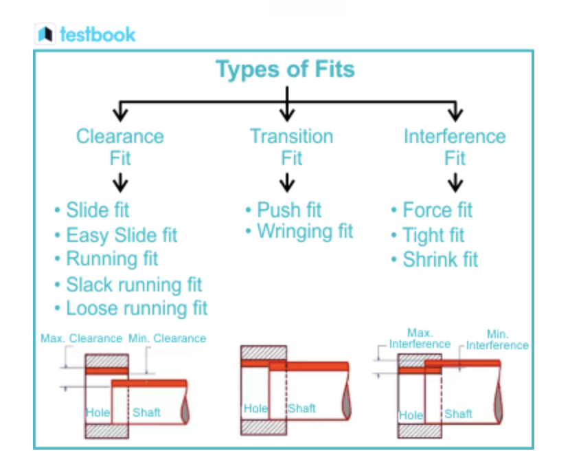
- Some people ask, what is a transition fit? The answer: It’s a compromise between a clearance and interference fit. It’s tighter than a fit with extra space, and things can move around (a clearance fit), but it’s not as tight as a fit where you have to force the pieces together (an interference fit). With this fit, you get a little wiggle room so the parts can come together without any need to force them, yet they’re still secure enough that they won’t come apart. It’s a good choice when you need parts lined up just right, like making a model or machine with moving parts.
- A sliding fit is an engineering fit where two mechanical components come together with a specific, intentional clearance. This fit allows one part to slide over the other without much resistance, enabling smooth motion. Sliding fits are standard in design applications that require relative movement between components, such as in sliding gears, clutch discs, and guide rails.
- Running fits are clearance fits of three types:
- Loose running fit: This represents the most significant clearance, suitable where accuracy is not essential.
- Free running fit: This fit works well where no specific requirements apply to the accuracy of matching parts. It provides movement in environments with temperature fluctuations, high-speed running, and heavy bearing pressures.
- Close-running fit: Close-running fits suit applications requiring smaller clearances, moderate accuracy, and withstanding medium speeds and pressures. Applications include machine spindles and sliding rods.
What are Tolerances, and Why Are They Important?
Tolerances are crucial in engineering since they define the permissible limits or variation in a physical dimension or measured value. Tolerances ensure that parts will fit together correctly, function as intended, and do so reliably over time. These specified ranges are necessary to protect the interchangeability of components and prevent equipment failures and safety issues. Tolerances are vital in manufacturing as they help to balance cost and function, striking a compromise between precision and the expense associated with achieving it.
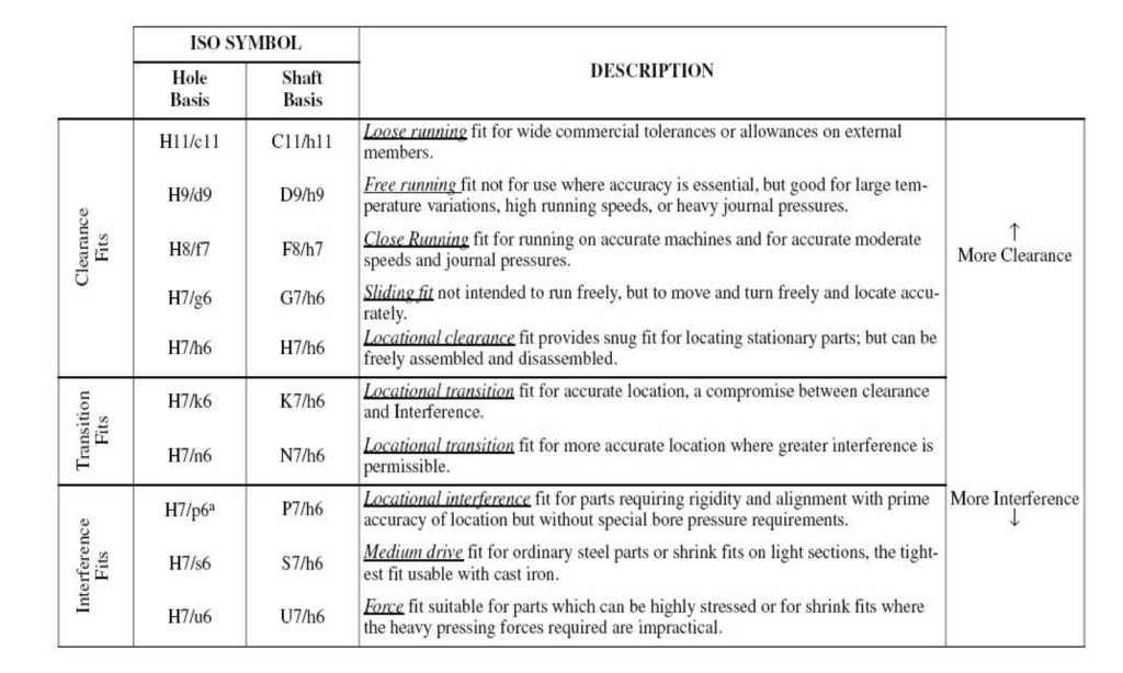
In engineering and manufacturing, h7 tolerance refers to a specific range where the size of a hole can vary, ensuring a standard level of snugness or looseness when paired with a shaft. For instance, an h7 fit would accommodate a slightly looser fit than an h6 fit, which allows for a tighter mating with less clearance. See the following fit chart:
Book a 60-minute demo to see
how eziil mrp solution works for you
Description of Preferred Fits (ANSI B4.2)
What are Some Engineering Applications of Limits and Fits?
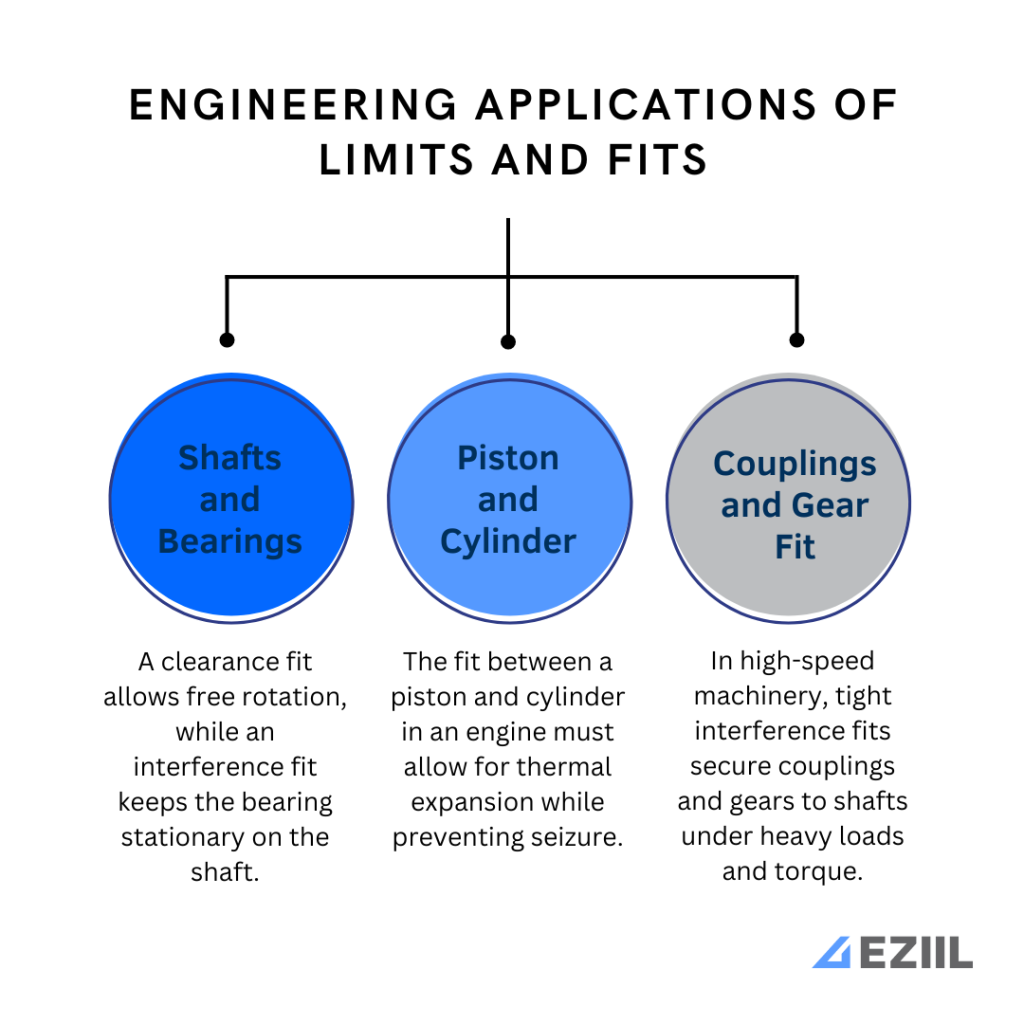
Limits and fits are crucial for the design and assembly of machine parts. Here are some practical examples:
- Shafts and Bearings: A typical example is when a shaft fits into a bearing. A clearance fit is necessary for a bearing that needs to rotate freely on a shaft. Conversely, a transition or interference fit might be used for a bearing that must remain stationary concerning the shaft.
- Piston and Cylinder: The fit between a piston and the cylinder in an internal combustion engine is another common application. This fit has to be precisely engineered to allow for thermal expansion while maintaining enough clearance to prevent seizure during operation.
- Couplings and Gear Fit: In high-speed machinery, tight interference fits are required for couplings and gears to ensure they remain securely attached to shafts under heavy loads or during torque transmission.
How Do Manufacturers Verify Fits and Tolerances?
Precision in manufacturing is essential to ensuring the quality and functionality of finished products. Various techniques and tools measure and verify fits and tolerances, which are critical for parts to assemble correctly. Calipers, micrometers, and gauges can provide accurate measurements down to close tolerances.
Additionally, coordinate measuring machines (CMMs) and laser scanners offer advanced capabilities for verifying complex geometries and ensuring that parts meet stringent specifications. This attention to detail in measurement and quality control is instrumental in preventing material waste, ensuring product reliability, and maintaining consumer trust through consistently delivering high-quality products.
Future Trends and Innovations in the Field of Limits and Fits
Emerging trends and technological advancements are significantly influencing the field of limits and fits, mainly through the integration of precision engineering and digital modeling. Computer-aided design (CAD) and computer-aided manufacturing (CAM) allow engineers to achieve tighter tolerances and more intricate fits that improve the lifecycle and performance of mechanical components.
Innovations like 3D printing and additive manufacturing are pushing the boundaries further by enabling rapid prototyping and creating complex geometries that were previously challenging or impossible to produce with traditional methods. These advancements enhance product quality, streamline the manufacturing process, and accelerate innovation in various industries.
Final Thoughts
The precision of engineering components is critical for the functionality and longevity of mechanical systems. The concepts of limits and fits are essential to understanding how parts interact, ensuring the right balance between looseness for movement and tightness for accuracy.
Knowledge of limits and fits is indispensable, whether it’s for manufacturing machine parts, aligning aerospace components, or assembling consumer products. The meticulous calculation and application of these engineering tolerances ultimately lead to the optimal performance and reliability of assembled equipment.