Learning to read blueprint symbols is challenging. There are so many different types of drawings, including architectural, mechanical, electrical, etc., that it’s impractical to cover all of them at once. So, we will focus on the basics of a machining drawing, and some of that information will help you learn the other types of drawings if you decide to go further.
What is a Blueprint?
Reading blueprints is an essential skill for anyone involved in the construction or manufacturing industry. Blueprints, also known as technical drawings or engineering drawings, are detailed and precise plans that are used to communicate design specifications and other essential information about a project. These drawings are typically produced by architects, engineers, or drafters, and they are used by contractors, builders, and other professionals to ensure that a project is constructed or manufactured to the correct specifications.
Overall, reading blueprints is an essential skill for anyone involved in the construction or manufacturing industry. It requires a combination of technical knowledge, spatial reasoning skills, and attention to detail, as well as an understanding of the underlying principles of engineering. By mastering the art of reading blueprints, professionals can ensure that projects are constructed or manufactured to the correct specifications, reducing errors and improving efficiency.
What are the Crucial Features of a Blueprint?
Some CNC machinists mistakenly believe that since parts are drawn on high-tech CAD programs, blueprints have outlived their usefulness, and learning to read them is a waste of time. However, blueprint reading remains essential because companies still use paper drawings for new parts, or machinists might have to run existing parts on old drawings.
Learn more about the types of CNC machines.
Whatever the reason, blueprint reading is not out of style, and it continues to be a much-needed skill. Here are some of its critical features:
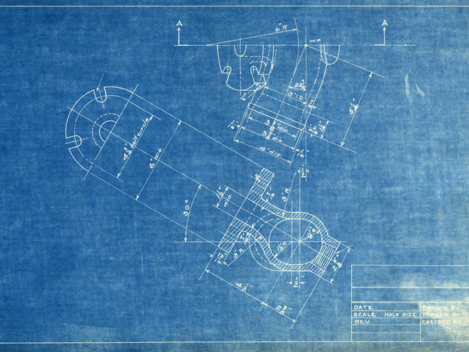
- Look at the key (legend) first: The key is in the bottom left or bottom right corner of the blueprint and contains the part name, part number, required tolerance, and part dimensions.
- Dimensions and tolerances on the part: The part’s dimensions and tolerances are often on the drawing of the piece instead of in the key. Looking at the dimensions helps you decide which tooling or machine tool you will use to machine it. The tolerances inform you which sizes are most critical. A word of caution: some dimensions are tight while others are not, so pay attention to every dimension on the drawing.
- Surface finish: Many blueprints specify the type of surface finish required.
- Part features: Most parts will have smaller features with separate dimensions and tolerances. These features include holes, threads, fillets, and rounds.
- General notes: These could be almost anywhere on the drawing, so be on the lookout for them.
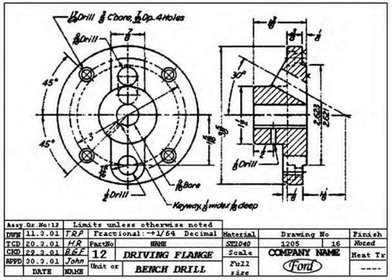
Image credit: Construction 53
What are Machinist Blueprint Symbols?
Engineering drawing is a fundamental skill in many branches of engineering, including mechanical, electrical, and civil engineering. It involves the creation of accurate, detailed drawings that convey all the necessary information about a design, including dimensions, materials, and other specifications. One of the key aspects of engineering drawing is the use of blueprint symbols, which are standardized symbols used to represent various components and features in a drawing.

What do the Various Lines on a
Blueprint Tell You?
Lines are the universal language of a machining drawing, and they have plenty to say. It’s a designer’s way of communicating the information the craftsman needs to create, assemble, service, or inspect a product, part, or component. Lines have a specific weight (thickness) and form that combine with other features to provide the information a skilled worker needs to understand the drawing.
Next are descriptions of the most common lines you’ll find on a blueprint, followed by a look at the lines themselves:
- Visible line: A thick continuous line outlining the edges or contours of an object.
- Hidden line: The hidden line shows edges, surfaces, and corners that cannot be seen. It is a medium-weight line consisting of short dashes about 1/8″ long with 1/16″ gaps.
- Centerline: Used to indicate the centers of holes, arcs, and symmetrical objects, the center line is a very thin long-short-long line.
- Dimension and extension lines: The dimension line is thin and solid, indicating the size of an object. Arrowheads at each end show where the dimension lines end at the extension lines.
- Short and long break lines: Break lines remove a section of a drawing for clarity, and shorten objects that are too long to fit on the drawing.
- Phantom line: Phantom lines are thin long-short-short-long lines that show the movement of an object, a part in an alternate position, or adjacent objects or features.
- Cutting plane line: A cutting plane line is heavy and shows the internal shape of a part by slicing through the object.
- Section line: Angled thin lines indicating cut surfaces in section views are called section lines.
- Leader line: Leader lines point to something on the drawing that requires clarification. The thin line is typically drawn at a 45-degree angle.
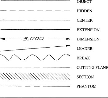
Image Credit: GlobalSpec
Understanding Construction Drawings and the Importance of Architectural and Blueprint Symbols
Construction drawings, also known as technical drawings or engineering drawings, are essential for architects, engineers, contractors, and builders in the construction industry. These drawings provide detailed information about a construction project, including dimensions, materials, and other specifications. In order to understand construction drawings, it is important to be familiar with the different types of symbols that are commonly used, including architectural symbols and blueprint symbols.
Architectural symbols are a type of symbol used in construction drawings that represent various architectural features of a building. These symbols include shapes, lines, and other markings that provide information about the design and layout of a building. For example, a square with an X inside may represent a window, while a triangle with a dot inside may represent a door. Other architectural symbols may include symbols for stairs, elevators, and plumbing fixtures.
Blueprint symbols, on the other hand, are a type of symbol used in technical drawings that represent various components and features of a project. These symbols include circles, squares, triangles, and other shapes that provide information about the size, shape, and location of different components. For example, a circle with a cross inside may represent a light fixture, while a square with a diagonal line may represent a switch. Other blueprint symbols may include symbols for electrical outlets, HVAC equipment, and plumbing fixtures.
Understanding construction drawings and the different types of symbols used in them is essential for anyone involved in the construction industry. By being able to interpret these drawings accurately, architects, engineers, contractors, and builders can ensure that a project is constructed to the correct specifications and meets all necessary regulations and codes. Additionally, being able to read and interpret construction drawings can help to reduce errors and improve efficiency during the construction process, saving time and money in the long run.
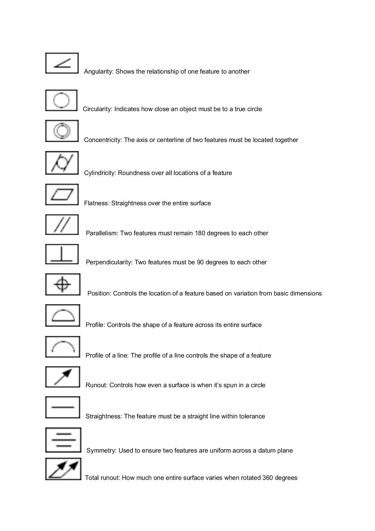
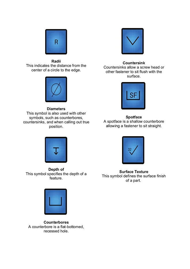
A Few Machinist Blueprint Symbols
to Apply to Features
Here are some of the other symbols you’ll encounter as you learn to read blueprints:
Blueprints are a Universal
Form of Communication
Blueprints are an essential element in machining since production cannot begin without them. They tell you how a finished product or part is expected to look and give you a detailed set of instructions for how to make that happen.
From a simple hub with three drilled holes to the most complex sub-assemblies that must fit together at the end of a project, blueprints make it all happen, and you can participate after you learn to read blueprints.