Even if you don’t work in manufacturing, you’ve probably heard of a “chamfer” but might not know what it is. Often, people think of a chamfer as just a finishing touch to make a part look nice. But chamfering is more than just making things look good. It’s really important for making parts work better and safer. In this guide, we’ll show you why chamfering is so important and what you need to know about it.

What is a Chamfer?
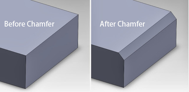
Image credit: https://leadrp.net/blog
Practically anyone associated with manufacturing will be familiar with the chamfer. They are angled surfaces machined along the edges of a workpiece that act as transitional areas between two intersecting faces of an object. Chamfers are typically designated as different sizes, depending on the application.
A chamfered edge usually has no operational requirement other than to protect the part or prevent cut fingers from a sharp edge. If two objects must fit together, the chamfer provides a smooth “lead-in” for the fit. Designers can instruct with “break all edges” on the drawing and indicate a chamfer size, or they can add a note specifying that all sharp edges should be deburred. The terms “break edge” and “deburr” are similar.
Chamfered edges are a common feature in manufacturing, and they can be found in a wide range of products and components. They are often used in metalworking applications to remove sharp edges and create a more aesthetically pleasing finish. In addition, chamfered edges can be used to improve the functionality of a part or component by providing a smooth transition between two surfaces.
The size and shape of a chamfered edge will depend on the specific application and the requirements of the part or component. In some cases, a small chamfer may be sufficient to provide the desired effect, while in other cases a larger chamfer may be required. Designers and engineers must carefully consider the application and the requirements of the part or component when determining the appropriate size and shape of the chamfered edge.
Chamfer vs. countersink: Are They the same?
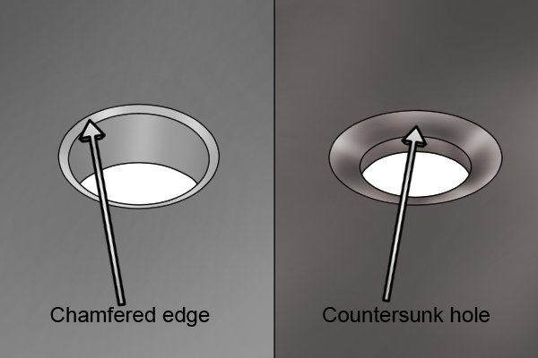
Image credit: https://www.wonkeedonkeetools.co.uk
Not exactly. Countersinks are chamfers, but they apply to round holes only. Another difference is that chamfers are usually specified at 45 degrees, while countersinks have angles of 82, 90, 100, and 120 degrees. Countersink angles are shown as the angle between two opposite sides, doubling their specified angle. In other words, a 45-degree chamfer would appear on the drawing as a 90-degree countersink.
What’s the Difference Between a Chamfer and a Bevel? How about a Fillet?
There are two schools of thought on whether a chamfer and a bevel are the same. Some contend they are the same, while others argue they are fundamentally different. To the latter, a chamfer removes the sharp corner of a part, but a bevel is a continuous angled surface between two parallel sides.
On the other hand, fillets are rounded edges on a workpiece, helping to reduce stress and making it easier to hold. A fillet’s geometry typically makes it more expensive and time-consuming to machine than a chamfer since it requires specific radius cutters for each fillet size. However, a single chamfer tool can machine various chamfer sizes.

Image credit: https://www.cnccookbook.com
The Importance of Chamfers
and Bevels in Welding
Chamfers and bevels prepare metal for a welded seam by cutting an angle on the edge of the piece. Although there are ways to add bevels and chamfers, including hand grinding and flame cutting, machining is neat, quick, and safe. The chosen method is often determined from the drawing or blueprint.
Here’s the information needed to get the correct bevel or chamfer:
The degree of angle: The standard slope is a 37.5-degree angle for pipe, but that will change for other applications.
The length of the bevel: This measurement is designated along the hypotenuse of the angle and is sometimes referred to as the “land” or the material remaining on the workpiece. The length must be consistent.
There are several welding bevels and symbols with which to become familiar.
How are Chamfers Dimensioned?
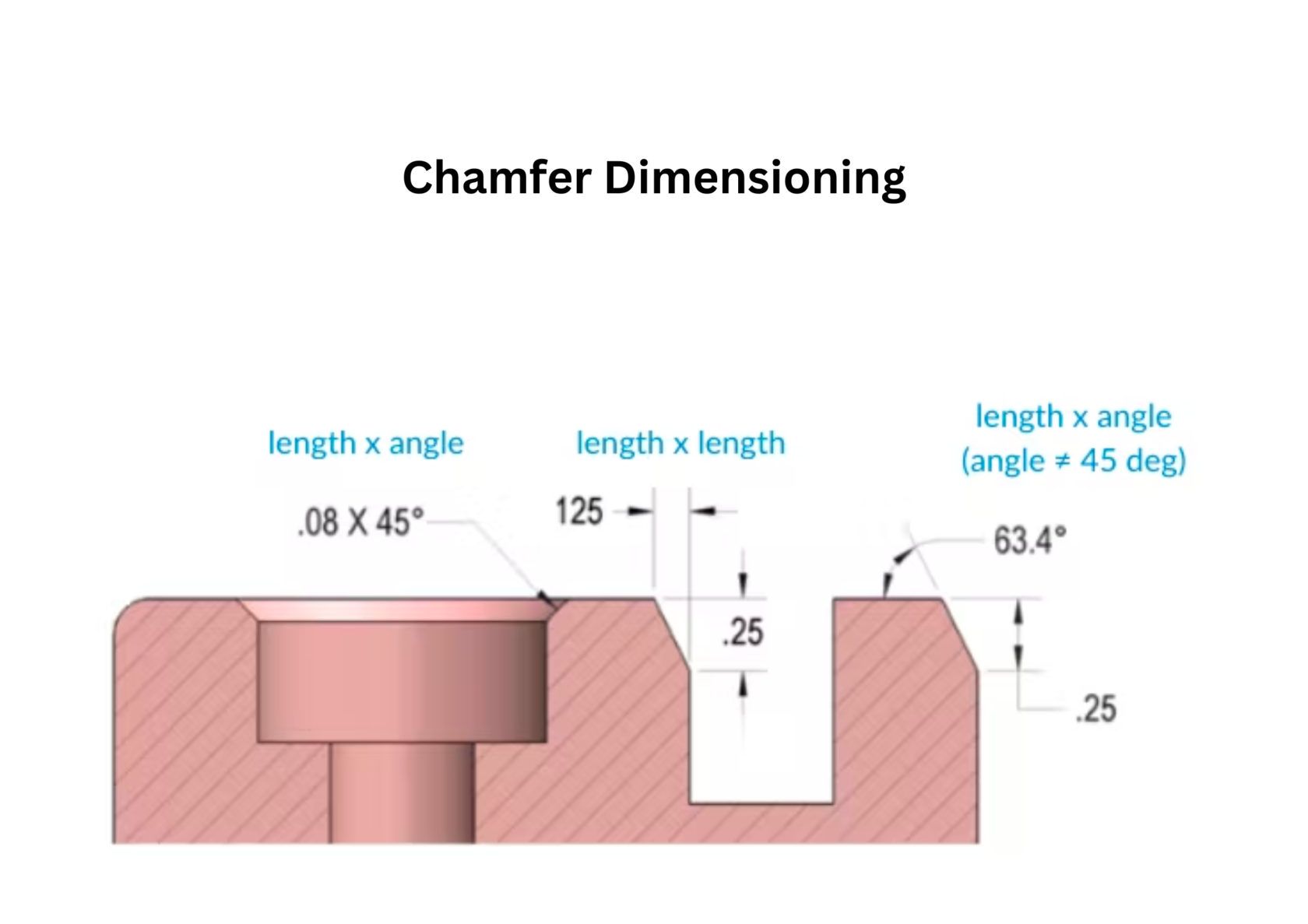
Dimensioning chamfers is accomplished in two ways: by denoting the length by angle or the length by length. Although most chamfers are 45 degrees, if they are any other angle, the surface to which they are measured must be clearly shown on the drawing. See below for chamfer dimensioning examples:

How to Measure a Chamfer
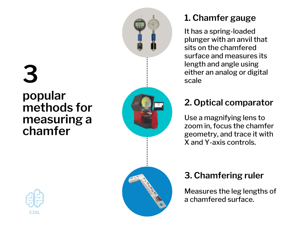
Dimensioning a chamfer is relatively straightforward, but how does an operator or quality-control inspector measure it? The most common chamfer angle is 45 degrees, but different tools, such as a chamfer gauge, optical comparator, or chamfering ruler, are available to measure it.
Here are the details of these three popular methods for measuring a chamfer:
Chamfer gauge
The chamfer gauge is specifically designed to measure the chamfer dimensions. It has a spring-loaded plunger with an anvil that sits on the chamfered surface and measures its length and angle using either an analog or digital scale. The digital model is more accurate and easier to use. Chamfer gauges are precise, typically within 0.01 mm (0.0004 inches).
Optical comparator
Optical comparators are another way to measure chamfers. Digital comparators use a magnifying lens to zoom in, focus the chamfer geometry, and trace it with X and Y-axis controls. Newer models allow users to measure the length and angle of the chamfer.
Chamfering ruler
A chamfering ruler measures the leg lengths of a chamfered surface. Merely position the ruler on the horizontal and vertical sides of the workpiece and measure the leg lengths. After getting the leg length of the chamfer, you can calculate its angle using basic trigonometry.
Chamfer Mills Make the Operation Simple
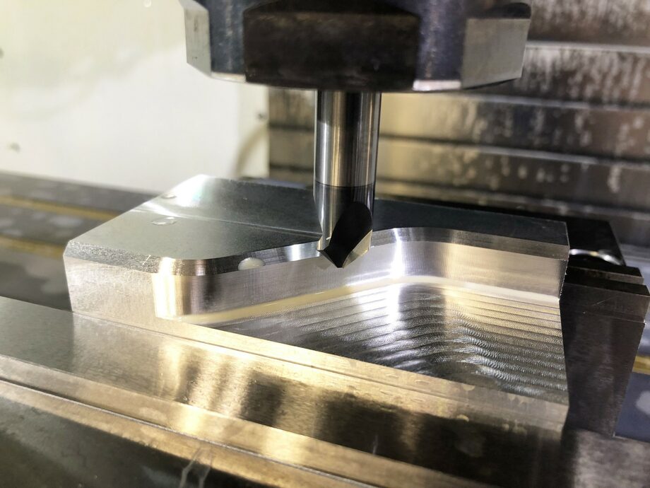
Machinists often use a chamfer mill to remove the sharp edges from a workpiece. The chamfer mill removes the edges and leaves an angled surface, typically a 45-degree chamfer, making the part aesthetically appealing, stronger, and safer. This versatile tool offers other benefits, including deburring, beveling, countersinking, and spotting.
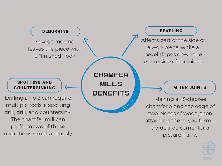
- Deburring: Using a chamfer mill to deburr a part during a CNC machining operation saves time and leaves the piece with a “finished” look. The tool’s angled cutting surface is ideal for deburring, requiring only a tiny adjustment to the program to make the shallow cut.
- Beveling: Although the terms “chamfer” and “bevel” are sometimes used interchangeably, they are slightly different. A chamfer affects part of the side of a workpiece, mainly the edge, while a bevel slopes down the entire side of the piece. In either case, the chamfer mill can machine it.
- Spotting and countersinking: Drilling a hole can require multiple tools: a spotting drill, drill, and countersink. The chamfer mill can perform two of these operations simultaneously. Using a sharp chamfer cutter with a diameter larger than the hole being drilled, the hole is spotted and countersunk before it is drilled. Remember that countersinks are not always 90-degree included angles, so the 45-degree chamfer mill will not be appropriate for every countersunk hole.
- Miter joints: A chamfer mill is sometimes used when making a miter joint. By making a 45-degree chamfer along the edge of two pieces of wood and then attaching them, you form a 90-degree corner for a picture frame.
The Role of Mechanical Engineering in Chamfering Processes
Mechanical engineering plays a critical role in chamfering, a process that is commonly used in manufacturing, machining, and engineering applications. Chamfering is the process of cutting or grinding a beveled edge onto a workpiece or part, typically at a 45-degree angle. The purpose of chamfering is to remove sharp edges, improve the appearance of the workpiece, and make it easier to handle and work with.
Mechanical engineers are involved in chamfering in several ways. First, they are responsible for designing and developing the machines and tools that are used in the chamfering process. This includes machines such as chamfering mills, chamfering machines, and grinding wheels, as well as the cutting tools and other accessories that are used with these machines.
Second, mechanical engineers are involved in determining the optimal parameters for chamfering a particular workpiece or part. This includes selecting the appropriate cutting speed, feed rate, and depth of cut, as well as the type of cutting tool and grinding wheel to be used. They also consider factors such as the material of the workpiece and the desired dimensions and tolerances of the beveled edge.
Finally, mechanical engineers are involved in the testing and quality control of chamfered workpieces and parts. This includes measuring the dimensions of the beveled edge to ensure that it meets the required specifications, as well as testing the strength and durability of the workpiece or part to ensure that it is fit for its intended purpose.
Chamfering is an important process in mechanical engineering and is used in a wide range of applications, including the manufacturing of machine parts, automotive components, and electronic devices. The use of chamfering helps to improve the quality and precision of the finished product, as well as reduce the risk of injury or damage that can result from sharp edges. By utilizing their expertise in machine design, process optimization, and quality control, mechanical engineers play a critical role in ensuring the success of chamfering operations and the production of high-quality beveled edges in various industries.
Chamfering Best Practices
Because chamfering is often an afterthought, its value is sometimes diminished. Think of it as adding molding to a remodeled room: it gives the finishing touch that makes the entire room neat and professional looking.
Yes, you could do chamfering with a hand tool, but chamfering your edges with a chamfer mill will provide your parts with consistency, aesthetics, and safety. Take your chamfers seriously and invest in tooling that gives your parts and components a high-quality appearance.