Technical drawings are also called ‘engineering drawings,’ and they describe three-dimensional parts and components through the means of two-dimensional paper. Producing technical drawings is often referred to as ‘drafting’ or ‘designing,’ These drawings come in various types, such as engineering detail drawings, production drawings, and assembly drawings. But no matter which type of drawing is used, its purpose is the same: they are created as standardized tools for conveying information without verbal exchanges and despite language barriers.
Among the different types of technical drawings, assembly drawings are essential for identifying each part of a machine or system in its operating position and assembly sequence.
Assembly drawings include a bill of materials (BOM), often called a parts list, sections, weight, and orthogonal plans.

The drawings are a universal graphic language spoken between a technical designer and a skilled operator to convey crucial instructions. Because of this, the draftsperson or designer must have an in-depth technical knowledge of the principles and practices of drafting to avoid misinterpretation and possibly litigation.
Additionally, the person “reading” these drawings must be skilled in understanding the graphical language used in the assembly drawings.
Assembly drawings are prepared either manually or with the help of computer-aided design (CAD) software, including Solidworks, Autodesk Fusion 360, and AutoCAD, the most widely used CAD software.
The drawings are then printed on standard-size paper.
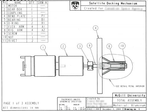
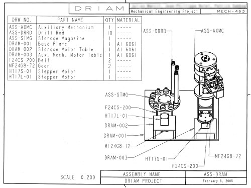
See two assembly drawing samples below (image credit: https://www.mcgill.ca):
Assembly drawings are used to both describe how parts are put together and explain the function of the entire unit.
Here are five types of assembly drawings
and how they are used:
Although there are several types of assembly drawings, here are the five most common:
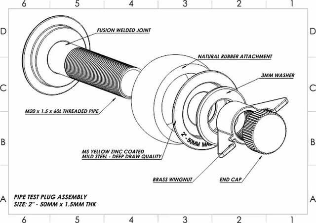
Image credit: https://www.cadcrowd.com
1. General assembly drawings
General assembly drawings identify the various components and their relationship. It contains the component’s detailed drawing, the sub-assembly, and the final assembly. The drawing can be divided into four categories:
a. Design drawings are made in the design stage and show machines, steel structures, and various constructions to be assembled from several angles. These drawings help visualize the object’s workings, including its shape and the clearances of specific parts.
b. Detailed drawings indicate how the components are assembled and provide specifics like the materials, dimensions, joining methods, etc. In addition to the regular assembly drawings, enlarged views of specific parts and how they will fit together can also be drawn up.
Some machinery and structures are made up of pre-assembled components, called sub-assemblies, and individual parts. They can be assembled and tested as a unit before they are put into their final assembly. A sub-assembly drawing will reference an assembly drawing.
c. Assembly drawings for catalogs are unique assembly drawings prepared for company catalogs. These drawings show only the relevant details and dimensions that interest a potential buyer.
d. Assembly drawings for instruction manuals are needed whenever a finished machine must be disassembled for shipping, reassembled, and installed at its destination. Each component in these drawings is numbered to aid in the reassembly process.
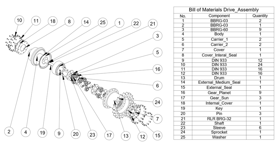
Image credit: https://help.bricsys.com
2. Exploded assembly drawing
These technical drawings show the components of an assembly slightly separated or suspended in space in the assembly sequence.
This “exploded” view clarifies how the final product will fit together, making it easier to understand even for a layperson.
These are the drawings found in parts catalogs, assemblies, manuals, or instructional materials.
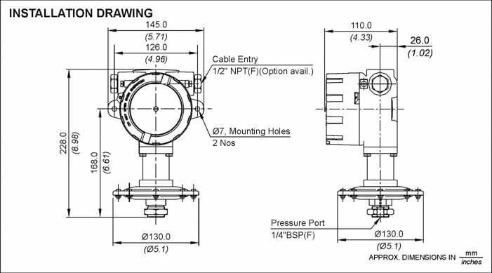
Image credit: https://www.designingbuildings.co.uk
3. Installation drawings
Installation drawings help workers with the erection or assembly of a product.
They supply information on how a component will be positioned in relation to its supporting or adjacent elements.
It will also show parts, dimensional data, hardware descriptions, and a general configuration.
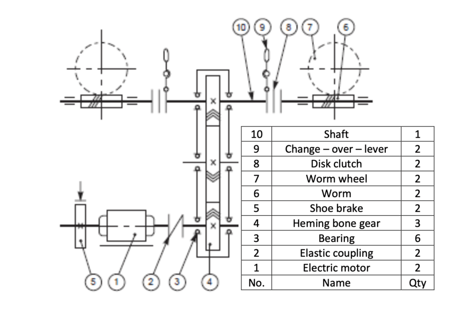
Image credit: https://www.uotechnology.edu.iq
4. Schematic assembly drawings
A schematic drawing is a simplified illustration of components using standardized symbols and lines. Schematic diagrams include only necessary details. For example, a schematic diagram of an electrical circuit will show how the wires and components are connected without photographs of the circuit itself.
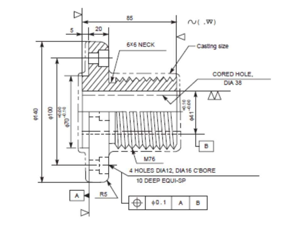
Image credit: https://www.uotechnology.edu.iq
5. Machine shop drawings
The machine shop drawings are for the machinist or machine operator. Because this person is unconcerned about information related to the previous stages or operations, only the information about the machined part’s function is included in the part drawing.

The Importance of Assembly Drawings
Producing any mechanism on a large scale will require numerous assemblies and sub-assemblies that must be accurately manufactured. Without assembly drawings, technical information would be communicated by speech or writing rather than graphical language, resulting in expensive misunderstandings, mistakes, and wasted time. The effective use of assembly drawings has been pivotal in safely producing vehicles, aircraft, and structures on which lives might depend.
Assembly drawings typically provide enough information to enable the assembly of a component, and they will usually include the following:
- Two or more parts or subordinate assemblies
- Sufficient orthogonal views showing how the parts fit together
- Section views to show how pieces fit and to reveal hidden details
- Dimensions are not shown on assembly drawings unless to indicate the overall size of the assembly or for machining operations needed for assembly.
- Requirements for processes, protective finishes, and other relevant data for completing the item as an assembly
- A bill of materials (parts list) specifying a unique identifier for items that become a part of the assembly
- The revision or issue information
What is Included in the Assembly Drawing’s
Bill of Materials?
A bill of materials is a complete list of the items comprising an assembly of detailed parts presented on a technical drawing. Whether included in the assembly drawing or as a separate document, the BOM provides valuable information to produce the items.
In vertical columns from left to right is the following information:
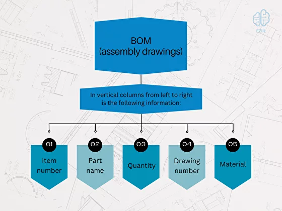
- Item number: The relevant item reference number is shown on the drawing and listed in sequential order
- Part name: Abbreviations may be used if they do not confuse. Use its traditional designation if the item describes a standard part, such as a nut or bolt.
- Quantity: The number of that specific part required for one complete assembly
- Drawing number
- Material
Conclusion
In conclusion, assembly drawings play an indispensable role in product design and mechanical engineering, as they provide essential visual representations of the assembly process for various parts and components. By utilizing a drawing sheet and assembly file, professionals can effectively communicate the intricacies of product assembly to engineers, manufacturers, and assembly technicians, ensuring a smooth transition from the design phase to the manufacturing phase.
A well-prepared assembly drawing, complete with dimensions and annotations added to the drawing sheet, ensures a clear understanding of the assembly process for all stakeholders involved. The addition of dimensions, tolerances, and other relevant information not only reduces the likelihood of errors during the assembly process but also contributes to the overall efficiency and success of the project.
The use of CAD software, such as SolidWorks, in creating assembly drawings significantly streamlines the process of generating new drawings from an existing assembly file. SolidWorks assembly drawing tools enable engineers to seamlessly integrate the 3D model with the 2D drawing sheet, simplifying the creation of orthographic views, section views, and isometric views. Furthermore, the software allows for the addition of dimensions, annotations, and exploded views directly onto the drawing sheet, providing a comprehensive understanding of the assembly process.
By harnessing the power of SolidWorks assembly drawing tools, professionals in product design and mechanical engineering can efficiently create detailed and accurate assembly drawings that serve as a valuable communication tool throughout the entire product lifecycle. These drawings ensure that all parties involved have a clear understanding of the assembly process, from the individual components to the final product or system, ultimately enhancing the overall success and efficiency of the project.
In summary, assembly drawings are integral to the field of product design and mechanical engineering, as they facilitate effective communication between all stakeholders and contribute to the successful completion of projects. By utilizing drawing sheets, assembly files, and CAD software like SolidWorks, professionals can generate detailed and accurate assembly drawings that showcase the assembly process and provide essential information for engineers, manufacturers, and assembly technicians. The addition of dimensions, annotations, and other relevant information to these drawings further ensures a clear understanding of the assembly process, ultimately leading to more efficient and successful projects in the realm of product design and mechanical engineering.