Identifying a suitable tolerance ensures the part’s manufacturer is aware of the critical dimensions in specific areas and focuses on them. Paying attention to these dimensional limitations is typically the difference between producing mating parts and those ending up in the scrap bin.
What Are Tolerances in Engineering?
Engineering tolerance is the permissible variation in measurements of a dimension or other measurable value from the designed size. Although tolerances can be applied to different units, such as temperature or humidity, mechanical engineers are primarily interested in tolerances on linear, angular, and other physical dimensions.
Tolerances instruct the manufacturer on an acceptable measurement range from the basic or nominal dimension. For example, if the nominal dimension on a shaft is shown as ⌀1.000 (+.000/-.001), the acceptable range of diameters is 1.000 as the maximum and .999 as the minimum. While this is a relatively simple example, tolerances also set limits on the most complex parts.
Whenever a dimension varies beyond the tolerance (the lathe operator turns the shaft to a diameter of .998), it is identified with terms like non-compliant, rejected, or exceeding the tolerance.
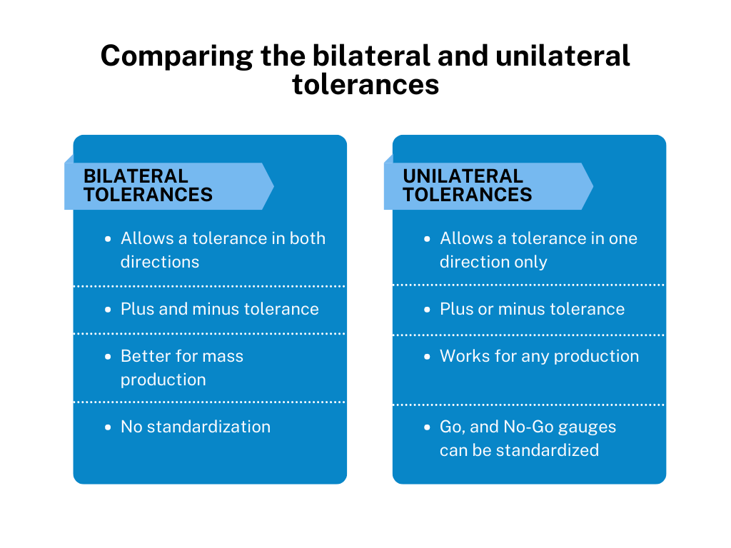
Next, let’s look at the two main types of tolerances: bilateral and unilateral.
What is a Bilateral Tolerance?
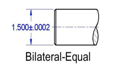
Bilateral tolerance is used when a two-limit dimension is above and below the nominal size. For instance, a shaft could have a measurement.
Example indicates that the shaft is within tolerance if it measures anywhere between 1.5002 at the upper limit (above) and 1.4998 at the lower limit (below). Bilateral tolerances can allow either equal or unequal variations on each side of the nominal size.
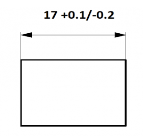
A block with unequal bilateral tolerances is shown below (mm):
What is Unilateral Tolerance?
Typically used to define tolerances in precision fit parts, unilateral tolerances feature dimensions where variations are only allowed on one side of the nominal size. An excellent example is when a .250 dowel pin must fit into a hole with a light press fit.
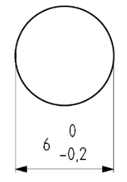
The designer will draw the hole with a unilateral tolerance: ⌀.2495 +.0000/-.0005. This will result in a press-fit ranging from .0005″ to .001″. In this case, either a ⌀.249 or ⌀.2495 reamer will provide a light press fit. On the example it is shown how a 6mm hole would be dimensioned for a press-fit.
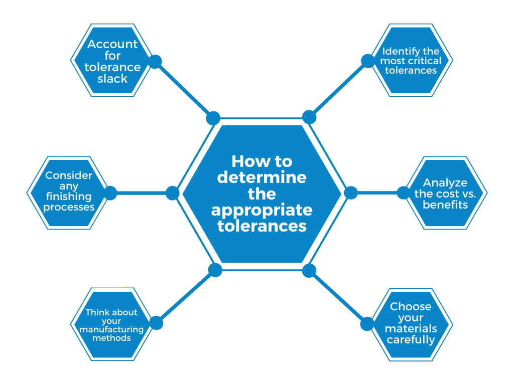
How to Determine the Appropriate Tolerances
Here are some things to consider before you meet with an engineer or designer to discuss tolerances on your part:
- Identify the most critical tolerances: Explain what you want your product to do and how the various components will work in an assembly.
- Analyze the cost vs. benefits: Tolerances must be tight enough for the part to work correctly, but remember that unnecessarily close tolerances are more expensive to produce.
- Choose your materials carefully: Some metals expand and contract in different temperatures or moisture levels. If you know the material will be stored in an environment that will affect the dimensions, adjust your tolerances accordingly.
- Think about your manufacturing methods: Different manufacturing requires different tolerances. For example, loosen your tolerances for weldments but tighten them for precision CNC machining.
- Consider any finishing processes: If you add metal plating to a part, for instance, you’ll need a new tolerance for the additional layer.
- Account for tolerance slack: Tolerance slack is the total maximum or minimum tolerance of a specific dimension. For example, if you have multiple components welded together side-by-side, each with a tolerance of ±0.5 mm, make sure you don’t exceed the tolerance on the total length of the fabricated part. If that could happen, you should tighten the tolerance on the individual components.
What is Geometric Dimensioning and Tolerancing (GD&T)?
GD&T is a design and manufacturing mechanism that helps engineers communicate to manufacturers how to build a part that matches the drawing and is precisely what the customer desires.
Machinists and designers use GD&T, print dimensions, and notes to create a manufacturing process that results in a high-precision component replicating the designer’s original vision. Proper detailing on the drawing enhances communication between the customer and vendor.
Using symbolic language, GD&T shows how much a part’s features may deviate from the geometries listed in the design model. This symbolic language has all the pertinent details involved in the manufacturing process, such as dimensions, tolerances, definitions, rules, and symbols communicating a component’s functional requirements.
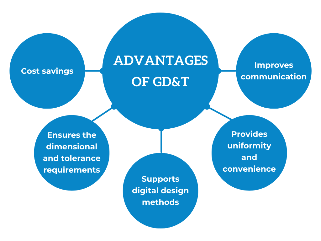
What are the Advantages of GD&T?
Engineers depend on GD&T to design every critical aspect of a part, including a specific feature’s location, form, profile, and orientation. GD&T is essential in complex machining because it provides numerous benefits:
- Cost savings: GD&T enables design accuracy by allowing appropriate tolerances that optimize production. The process often offers extra or bonus tolerances, which increase the savings.
- Ensures the dimensional and tolerance requirements: GD&T clearly states all conditions, providing all dimensional and tolerance specifications.
- Supports digital design methods: GD&T data is adaptable to digital design programs, including 2D and 3D CAD files.
- Provides uniformity and convenience: GD&T uses consistent language, eliminating guesswork and interpretation while providing uniform geometries in design and manufacturing.
- Improves communication: Complex designs require accurate and reliable communication. GD&T enables designers, manufacturers, and inspectors to communicate correctly, saving time and creating an efficient process.
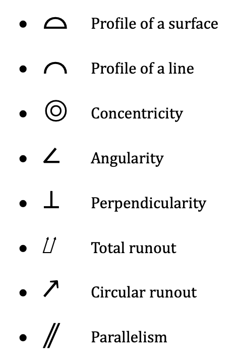
Common GD&T symbols
Why does tolerance matter?
A tolerance range gives the manufacturer an acceptable boundary for deviation. If your part requires a specific level of precision, the tolerance system communicates it and ensures you will receive the accuracy you need.
Suppose you do not include tolerances on your drawings. In that case, you are giving the manufacturer free rein to use their in-house standard, and these generic tolerances might not suffice if your components must fit together at the final assembly.
However, going overboard with close tolerances on every dimension could be costly. Determine which are the precision dimensions and stay loose on the others. Precision is expensive, and you don’t want to price your parts well above the competition for no good reason.