Welding symbols are shorthand codes placed on fabrication drawings that tell the welder what joint, where the weld sits, and how to execute it—size, length, finish and all. The tail of the symbol can add process notes such as TIG, MIG or ‘field weld’.
When designing parts for general metal fabrication, welding symbols, and detailed callouts will be required to communicate design intent and requirements effectively to manufacturers.
These callouts will be found on the technical drawings (or blueprint) of the assembly, also known as a weldment, and will specify weld geometry and its associated size and length requirements.

When interpreting a print, the welding symbol will contain all the appropriate information necessary to perform the proper weld on the part.
Welding symbols, which are different than weld symbols, contain information such as what weld symbol is being used (fillet, bevel, square butt, plug weld, etc.), the length of weld, the pattern of the weld (skip seam or full length), weld size, etc…
Welding symbols are a menagerie of information, and the combinations of designs and choices that can be made are significant.
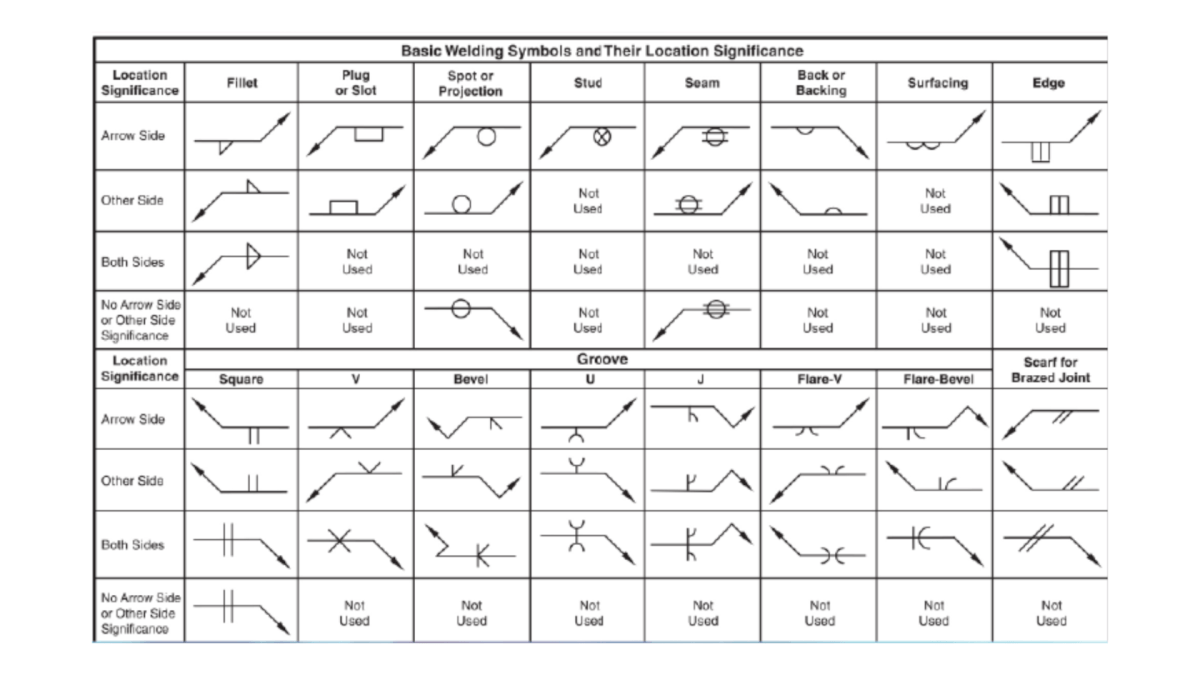
Image credit: https://welder101.com
Types of Welding
There exist a variety of welding processes to utilize, but ultimately welding processes are generally agnostic to the process, so long as the symbol callouts are satisfied during the fabrication process.
Weld Procedures are generated and used if specific welding processes are required, and these go even further to specify the filler material, any preheat requirements for the part, as well as heat input and feed rates allowed during the welding process.
The primary types of welding one could expect to see are Gas Tungsten Arc Welding (TIG), Gas Metal Arc Welding (GMAW), Shield-Metal Arc Welding (SMAW or Stick), and Flux-Cored Arc Welding (FCAW).
All of these common forms of welding are doing via a handheld torch and allow the welder to create welds per the specific welding blueprint for the particular weldment being created.
Welding Symbols
Welding symbols, also referred to as weld callouts and welding drawing symbols, contain information pertinent to the weld as previously mentioned.
Below is a comprehensive list of what one can expect to see on a welding symbol, as well as an example image and list of options for each aspect of the welding symbol.
The Arrow1
The arrow is used to locate the location of the weld, and has the reference line attached to its body. Within this reference line, all pertinent welding information will be displayed.
Image credit: https://www.weldingis.com
The Arrow Head
The head of the arrow is used to point directly to the spot that is expected to be welded on the blueprint. This arrow does not always have a straight section, it may be angled to pinpoint the exact location of the weld depending on geometry.
Circle Injunction
The circle injunction is seen on round geometries that will require a weld all around – it can also be referred to as the ‘all around weld symbol’ and specifies that every possible portion of the joint needs to be welded. In some cases the weld symbol is referring to a non-circular joint, in which case the circle injunction will not be present.
The Flag
The flag portion of the welding symbol is a callout to imply whether or not the weld is intended to be performed in the field. If the flag is present, the weld will occur in the field. If the flag is not present, the weld will occur in a manufacturing facility.
The flag is important to take note of as the process for welding will change dramatically based on the environment the welding will occur in.
The Reference Line
The reference line contains the bulk of the information about the weld. It will provide information on things like the joint design, the weld pattern, weld size, and many other elements.
The reference line is not always double sided or single sided – it can have two different types of information on the top and bottom, which implies that the top of the joint to be welded will receive a different type of weld than the bottom side. If there is no bottom side on the reference line, then only the top side of the joint will be welded, and vice versa.
Groove Design
There are various types of grooves that can be seen on joints prepared for welding, and this aspect of the welding symbol specifies which groove weld symbol is to be expected.
The most common groove designs in industry are the fillet weld and V-Groove, but there are many other types out there like the X Groove, I-Groove, and U-Groove.
The Weld Size
The weld size specifies the dimension of the actual weld itself once completed. This size effects the overall strength of the weld and can also affect how much distortion the part experiences during the welding process as a direct result of the amount of heat input.
There are two primary callouts for the weld size, S & E. S stands for size, and is most commonly seen on fillet welds. E stands for the effective throat of the weld and is most used in groove welding.
The Weld Pattern
The weld pattern is not a commonly utilized part of the welding symbol as most welds are full length, but essentially what this callout specifies is the pitch (center to center distance of the welds, P), and length (actual length of each weld seam).
Weld patterns are utilized when distortion or excessive material consumption is a concern on a weldment.
The pattern below is also referred to as a stitch weld, and the weld pattern callout is also known as a stitch weld symbol.
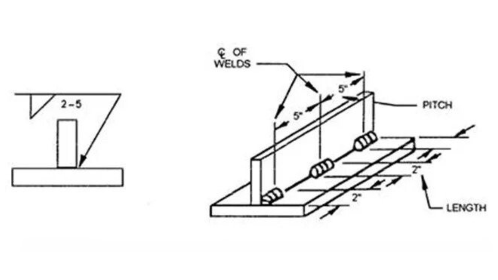
Image credit: https://www.weldingis.com

The Root Opening
The root opening is a symbol that will be seen on parts requiring a root-pass weld. A root-pass weld is a weld in which the parts are actually gapped apart with the open space to be a full penetration weld. Root pass welding is most found in pressure vessel applications.
The Bevel Angle
The bevel angle is the shape of the bevel between the two connecting parts at the weld joint. Bevel angle determines the overall effectiveness of the welder and their ability to get good penetration on their weld for proper welds to be formed.
The Contour
The contour is the callout that specifies the actual shape of the weld itself. This could be a convex weld (a weld that makes a rounded outward like a ‘hump’), a concave weld (a U-Shaped weld), or a flush weld in which the weld is flush with the two surfaces of the joint. The contour callout also implies information about the finishing symbol, too.
Finishing
The finishing callout is directly related to the contour callout and specify which process will be used to achieve the desired contour. The 3 primary methods of finishing are machining (M), surface grinding (G), and chipping (C)
The Tail Welding Symbol
The tail welding symbol is reserved for additional information that may be required that is not captured on the welding symbol itself. This information can relate to the post-weld examination process, refer to a specific welding procedure, and even provide additional welding information if needed.
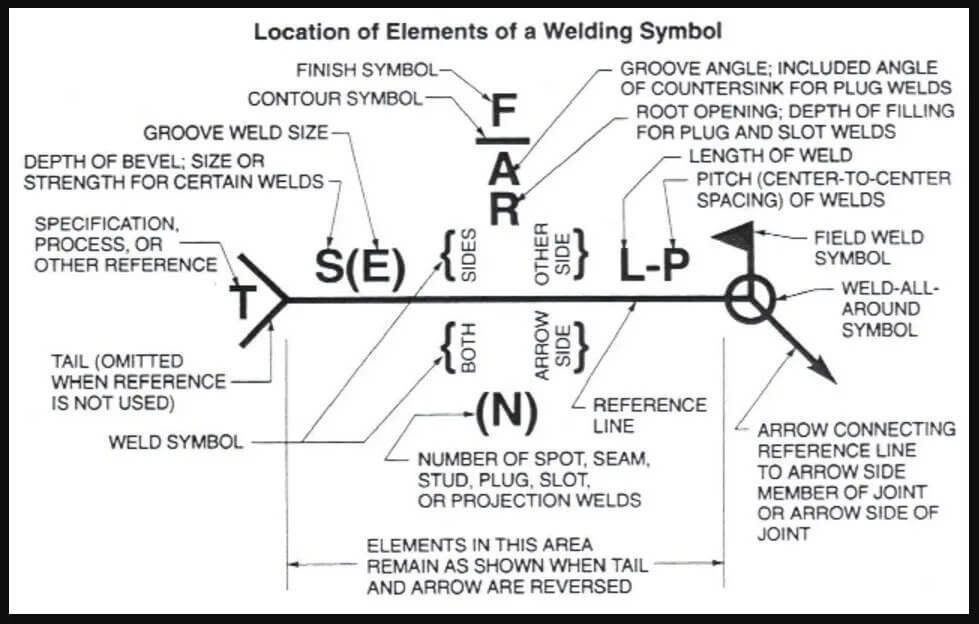
Image credit: https://www.weldingis.com
Weld Symbols
Weld symbols are found on a Welding Symbol, and they specify the geometry of the joint to be welded, as well as basic information about the weld. The American Welding Society (AWS) has a comprehensive list of basic welding symbols that can be seen below, as well as general groove welding symbols
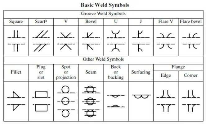
Image credit: https://www.weldingis.com
Groove Weld Symbols
Groove weld symbols specify the groove geometry to be welded, and let the welder know what to expect when preparing to weld the weldment. The most common groove weld symbol encountered is the bevel weld symbol, which can be broken down into a single bevel, or a double bevel which is also known as a V-Groove. When referring to the Basic Weld Symbols chart, note the different potential groove geometries and their visual representation of them.
Other Weld Symbols
The American Welding Society defines Other Weld Symbols as symbols that specify a weld geometry that does not involve a groove. There are a variety of other weld symbols, such as the spot-welding symbol, which is also used as an informal tack welding symbol, the plug weld symbol (which can also be used to denote a straight slot weld), and the most common fillet weld symbol.
Conclusion
Welding blueprint symbols and signs are of paramount importance in the realm of product design and mechanical engineering, as they provide a standardized visual language that effectively communicates the specifications and requirements for various types of welds and weld joints. These symbols, which adhere to guidelines set forth by the American Welding Society, facilitate clear communication among engineers, welders, and fabricators, ensuring a smooth transition from the design phase to the manufacturing phase.
Fillet welds, which are widely used in product design and mechanical engineering, are crucial for joining two pieces of metal at a right angle. By using the appropriate fillet weld symbol on the horizontal line of a welding symbol, professionals can accurately convey the necessary fillet weld requirements. Similarly, groove welds, which join workpieces along their edges, are also clearly represented on welding blueprints with distinctive geometric symbols, allowing for easy identification of the specific type of groove weld needed for a particular joint.
The horizontal line is an essential component of welding symbols, providing a reference line for all other welding symbols and dimensions. By placing fillet weld, groove weld, spot weld, and field weld symbols either above or below the horizontal line, engineers can effectively communicate the desired welding location and other relevant specifications. Additionally, weld metal specifications and standardized symbols for weld joints are indispensable for ensuring that the correct amount of material is used and that the proper joint configuration is achieved.
Spot welds, which are employed to join overlapping metal sheets, are also of great significance in product design and mechanical engineering. The use of spot weld symbols on the horizontal line enables professionals to accurately indicate the presence of spot welds and their specific locations. Furthermore, field weld symbols, denoted by a flag extending from the horizontal line, play a critical role in specifying that a weld should be executed in the field or on-site, as opposed to in a controlled shop environment.
In summary, welding blueprint symbols and signs serve as a vital communication tool in product design and mechanical engineering, enabling professionals to effectively represent various types of welds and weld joints on technical drawings. By utilizing the horizontal line, fillet weld symbols, groove weld symbols, spot weld symbols, and field weld symbols, as well as providing clear specifications for weld metal and weld joints, engineers, welders, and fabricators can work together to ensure a seamless and successful transition from the design phase to the manufacturing phase. This comprehensive visual language ultimately contributes to the overall efficiency and success of projects in the field of product design and mechanical engineering.