Sheet metal bending is a versatile field that enables the creation of designs from complex to simple in a cost-effective and efficient manner. Like all manufacturing processes, certain rules of thumb are crucial for designing features that simplify production.
This article will explore key terms related to sheet metal bend radius and their significance in design, alongside general rules that enhance manufacturability.
Differences in Materials
When doing sheet metal work, it is important to note that differences in materials will affect the overall design parameters allowable. A general assumption is that as materials get harder, their minimum bending radius gets larger. These differences in materials are important to keep in mind during the design process as they can ultimately cause issues during production.
Learn more about Sheet metal fabrication (types, materials, finishes).
General sheet metal Bend Radius Terms and Their Meaning
Bending Radius
Bending Radius refers to the minimum radius that can be applied to a sheet metal component where its flange originates from. Bending radii are usually dictated by available tooling, and for quick and effective design work it is recommended to speak with manufacturers so that design can be done around their standard operating procedures as well as available tooling.
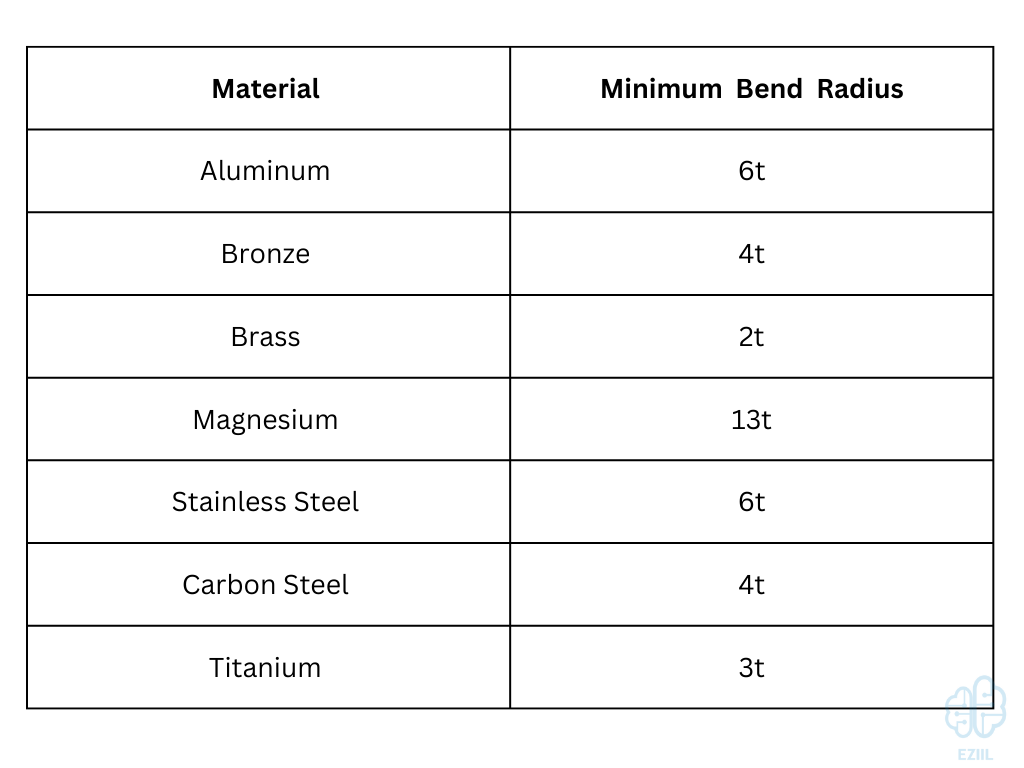
There is a minimum bending radius that should always be maintained in sheet metal design practices, and this minimum BR is displayed as a multiple of the specific raw material’s thickness. This value changes based on the type of material being bent as well. See below for details:
Bending Height
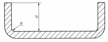
Image credit: https://www.machinemfg.com
Bending Height refers the to ‘length’ of flange after a bend is made from the main body. This height can be as large as desired, but there is a lower limit that should not be exceeded as a rule of thumb. This rule of thumb is that the Bending Height must be greater than or equal to the BR summed with two times the material thickness, or H ≥ 2t + R.
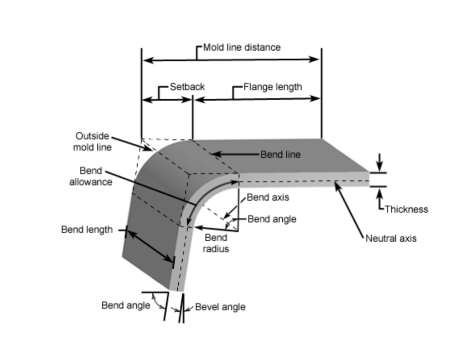
Image credit: https://www.custompartnet.com
Bending Direction
Sheet metal displays anisotropic behavior when being bent, and direction matters to prevent general manufacturing defects like cracks and tears during the bending process. If sheet metal is bent in line with the direction of the metal fibers, the likelihood of experiencing a crack or tear at the bend is much higher. Along with this risk of failure, the bend itself will be weaker than that of a bend done perpendicular to the metal fibers.
As a rule of thumb, bends should always be perpendicular to the metal fiber direction to increase the strength of the bend as well as reduce the overall risk of manufacturing defects from appearing during the production process.
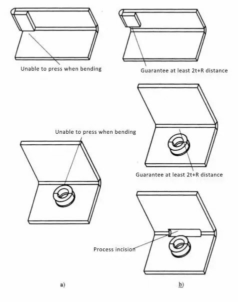
Image credit: https://www.machinemfg.com
Bending Tool Interference
When designing components for sheet metal bending operations, one should consider the clearance and accessibility of the desired bend by the tooling itself. If features are extending over the desired bend area, it is possible to prevent the bending operation from occurring as the features will block the tooling’s ability to bend at the appropriate location.
The minimum feature distance that should be utilized is the same as that of the minimum bend height. In other words, anytime an additional feature is added above a bend location, it should be spaced at least greater than or equal to the BR summed with two times the material thickness, or H ≥ 2t + R.
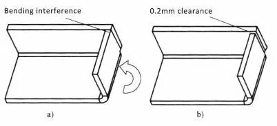
Image credit: https://www.machinemfg.com
Bent Flange Interference
When a box shape is desired or two walls will be bent at a shared corner, it is important to pay attention to the ‘shared’ space that both walls will intersect at. Typically, an offset on one wall is added so that it reduces the likelihood of the flanges interfering. The larger the offset, the greater the chance of a successful bend, but the harder the weld will be if the seams are meant to be welded together. In most cases, an offset of 0.2mm is adequate.

Bend Allowance in Sheet Metal Bending
Bend Allowance is a concept centered around the fact that when sheet metal is bent, there are 3 dimensions to consider. These dimensions are the outer radius arc length of the bend, the inner radius arc length of the bend, and the material thickness itself. For every bend created, the sum of the inner and outer radii arc lengths is always greater than the material thickness itself. The difference between this sum of radii arc lengths and the material thickness is known as the bend allowance.
Determining bend allowance is a relatively complex matter, and it is recommended that manufacturers be consulted to understand their specific design parameters around bend allowance. In speaking with the manufacturers, you will understand how they calculate the appropriate bend radius (typically identified through a standardized table) and increase the effectiveness of your designs with respect to overall manufacturability.
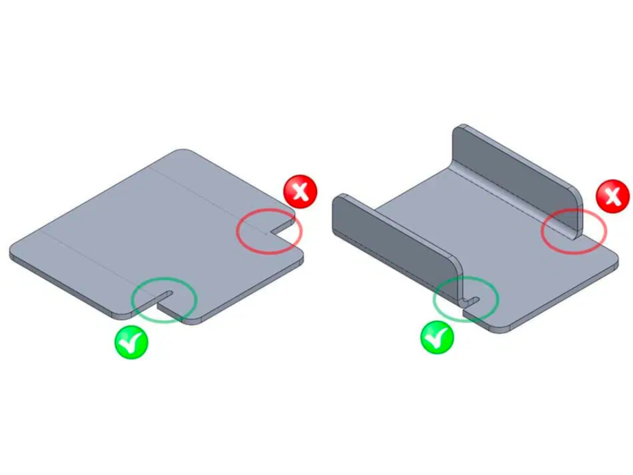
Image credit: https://sendcutsend.com
Sheet Metal Bend Reliefs
Bend reliefs are commonly found in sheet metal bending applications as they prevent the tearing or general failure of high stress points, commonly corners, during the bending process. Bend reliefs are simply two incisions cut into sheet metal in order to separate the separate bends that will ultimately take place. Sheet metal bends are only necessary when material will be present on either side of a bend.
Bend reliefs can increase the strength of the overall bend as well as reduce the risk of tearing during the manufacturing process. These reliefs can be done in any shape, but circular holes at corner seems or rectangular slits are generally the most common form of bend reliefs seen in the industry.
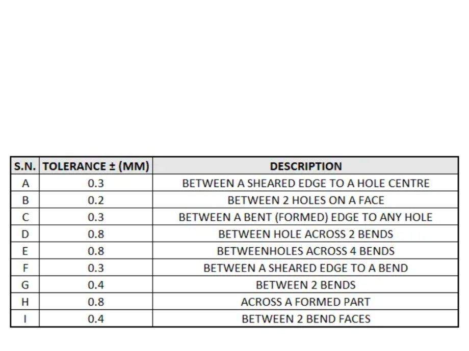
Image credit: https://factorem.medium.com
Tolerance Stackup and Sheet Metal Bending
It is important to note that as multiple bends compound off of each other, the likelihood of feature misalignment grows greater and greater. This likelihood of error and misalignment is caused by the relatively large tolerance band of sheet metal forming.
When working with multiple bends on the same part, it is advisable to speak with the final manufacturer to get their feedback on potential design considerations to avoid these issues. Ultimately, if the part is intended to be manufactured in large quantities, first article prototyping should be done until the desired outcome is achieved through standard design principles.
Some of these design principles include:
• Designing holes to be larger so that they absorb some of the variance in tolerance
• Incorporating alignment holes on the base of the sheet metal component so that the pieces can be mated together more easily during final assembly.
• Bending the components without the holes present, and adding the holes through additional post processing such as stamping or machining. While this approach has the highest chance of success, it is not recommended as the increase to overall production cost is not typically worth the ease of assembly.
Sheet metal bend radius is an essential factor to consider during metal forming processes like air bending or metal bending with a press brake. The bend radius refers to the curvature of a bend and is determined by the material type, thickness, and bend angle.
When performing metal bending, the tangent point is where the metal begins to bend, and the radius begins to form. It is crucial to maintain the tangent point at the correct location to ensure a proper bend radius. The metal bending tools and press brake used must be appropriate for the material type and thickness to ensure the correct bend radius is achieved without cracking or damaging the material.
The material type is a crucial factor to consider when determining the appropriate bend radius. The bend radius should be selected based on the material’s ability to withstand deformation and not cause any stress or damage to the material.
When bending sheet metal, the bend angle should also be taken into account. The bend angle refers to the angle formed between the two adjacent surfaces of the metal after bending. The bend radius required for a particular bend angle will depend on the material type and thickness.
To achieve the correct sheet metal bend radius, it is crucial to use proper techniques, equipment, and tooling. Using the appropriate press brake and metal bending tools and following proper air bending or metal bending procedures can ensure a consistent and accurate bend radius. With careful consideration of all the factors involved, including material type, thickness, bend angle, and tangent point, high-quality sheet metal bending with the desired bend radius can be achieved.

Conclusion
When designing products that will be comprised of sheet metal, there are many key rules of thumb to keep in mind. Primarily, sheet metal bend radius, bend height, and bend allowance will dictate a majority of your design choices as you progress on your concept. Other factors such as bend relief geometries and flange offsets will complete your design choices and yield a quality design that is suitable for production. It is always recommended to reach out to the intended manufacturer(s) to get their input and understand their specific capabilities that will ultimately dictate your design choices.